
MEP clash detection helps prevent costly construction problems by identifying competing service routes and insufficient clearances before affected work is fabricated or installed. Its value comes from resolving those findings, checking the revised design and issuing coordinated construction information. A clash report alone does not protect a project budget.
MEP means mechanical, electrical and plumbing. These systems share space with the building structure, ceilings and architectural finishes. On Saudi commercial and industrial projects, an unresolved conflict can affect several trades at once. This guide explains the connection between a model finding and a construction consequence, using practical examples rather than unsupported savings figures.
Building information modelling, or BIM, gives project teams a three-dimensional representation of building elements. For coordination, discipline models are brought together into a federated model. Designers continue to maintain their own source information while the combined view reveals how the systems fit together.
A hard clash identifies intersecting geometry, such as a duct crossing a concrete beam. A clearance check examines whether objects approach within an agreed distance. It can help test separation or reserved space, provided the required geometry and rules are included. Definitions and settings vary between tools, so the project should state its test terminology.
MEP coordination also involves engineering judgement. The software can locate an intersection; it cannot decide whether a new duct route maintains airflow, whether a drainage route preserves its fall, or whether an opening is structurally acceptable. The relevant designers must evaluate the solution.
Autodesk’s clash-test documentation distinguishes physical intersections, clearance checks and duplicate geometry. Agree which checks the project needs.
Consider a prefabricated duct section that cannot pass beneath a beam without entering the approved ceiling zone. If the conflict is discovered during installation, the team may need to stop work, redesign the route and remake the duct. Other services may need to move as well.
The commercial consequence can include wasted material, removal and reinstatement labour, revised supports, additional access equipment and repeated inspections. Delayed ceiling closure can affect finishing activities. The actual effect depends on the programme, contracts and work already completed; a model intersection does not automatically establish a payable variation.
Early resolution changes the decision point. A coordinated alteration made before fabrication can be incorporated into the correct production information. The objective is to avoid committing labour and material to an unresolved layout, while preserving the engineering performance of the revised system.
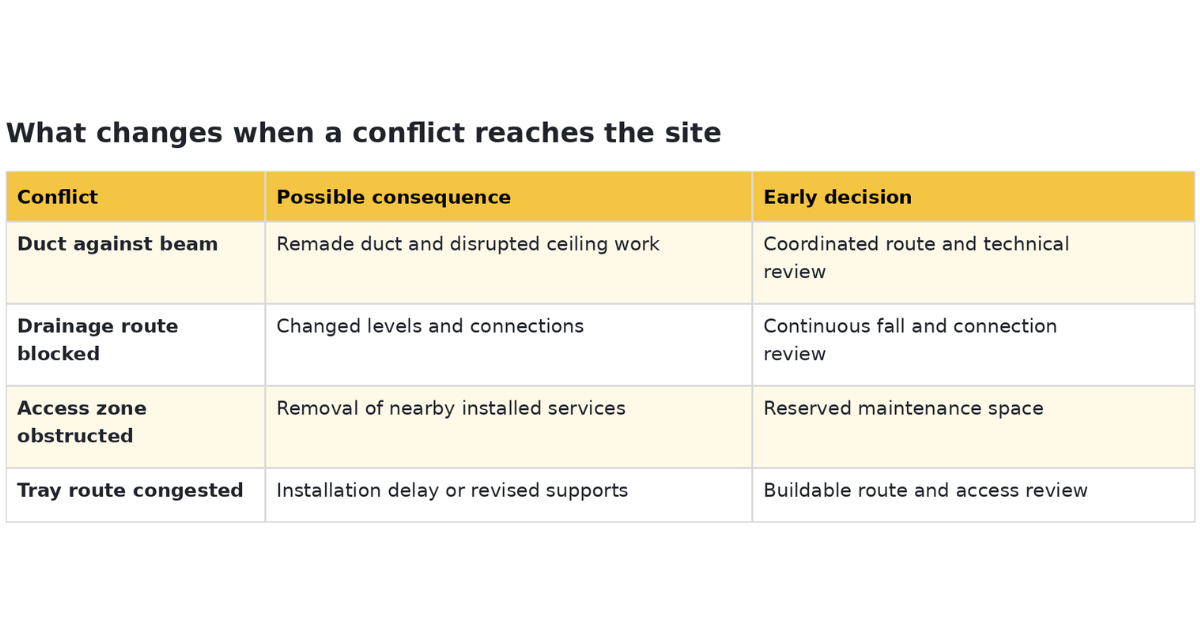
Service-to-structure conflicts need immediate attention when the proposed route intersects a beam, slab or wall. A structural opening must be reviewed by the structural designer. Site cutting or drilling should never become the assumed solution simply because a service is difficult to route.
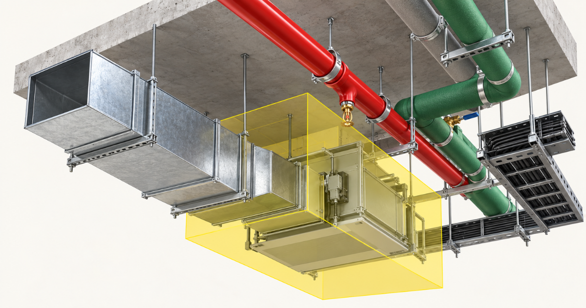
Congested ceiling zones often combine ducts, fire pipework, cable trays and lighting. Review full outside dimensions, insulation and supports where required by the coordination scope. A bare pipe model may appear to fit even though the insulated assembly does not.
Drainage conflicts are different from many pressurised services because gravity pipework needs an appropriate continuous fall. Moving a pipe around a duct can change its levels and connection arrangement. Recheck the complete route, rather than closing the clash at one isolated point.
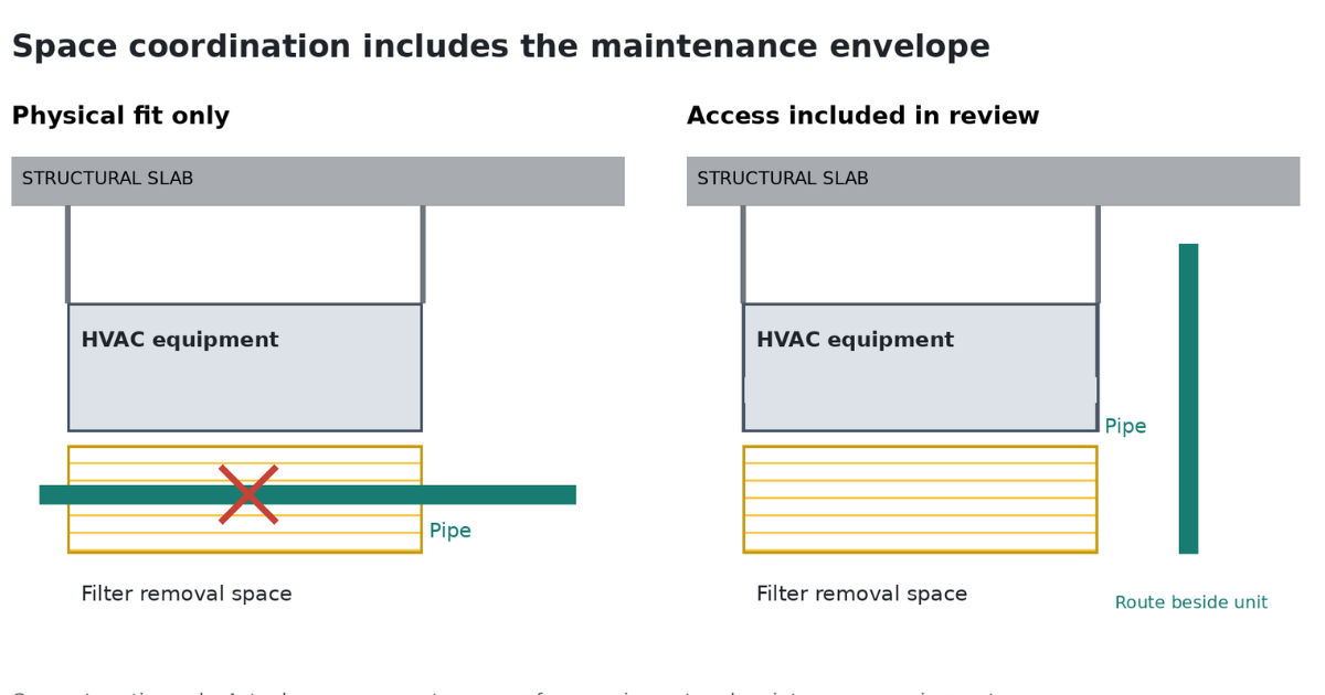
Equipment-access conflicts may remain invisible if only the physical unit is modelled. Reserve filter withdrawal, valve access, panel opening and component removal space from the relevant manufacturer and maintenance requirements. A service can avoid the unit itself yet obstruct the work needed to maintain it.
Electrical distribution conflicts can block cable installation or access to trays and equipment. Review the required working and installation space with the electrical designer. Any rerouting also needs checks for support arrangements and the applicable system requirements.
At concept design, use BIM coordination to test broad space reservations: risers, plant rooms, main service zones and major structural interfaces. The model may not yet contain fabrication detail. Treat this as a spatial feasibility review rather than proof that every installation fits.
During detailed design, resolve routes, opening locations, equipment positions and significant access zones. Before procurement or fabrication, incorporate the selected products and the agreed level of detail. Substituted equipment can change dimensions, connections and service requirements even when its nominal duty is similar.
Recheck affected areas after a design change. For a Riyadh retail fit-out, for example, a tenant’s revised ceiling feature can alter a previously coordinated duct zone. A model that was clear last month cannot establish the suitability of today’s revised arrangement.
Begin with common coordinates, agreed units and a revision register. Misaligned models can produce false conflicts, while omitted or superseded files can conceal real ones. Identify the area and design stage covered by each review so recipients understand its limits.
Agree a clash matrix: the list of system pairs and rules to be tested. Include the relevant architecture and structure, not just MEP against MEP. Record exclusions and tolerances. A large tolerance may suppress relevant findings; an unsuitable test can generate excessive noise.
Define how insulation, supports, access envelopes and builder’s-work openings are represented. The required model detail should match the decision being made. A fabrication release needs different evidence from an early layout discussion. The appointed team should document responsibility for producing and checking that information.
Check test exclusions against the Navisworks clash-rule guidance if that tool is used. Rules should remove irrelevant findings without concealing important interfaces.
First confirm that the finding is real and relevant. Duplicate geometry, intended connections and inaccurate exports can require model correction rather than redesign. Group findings that share one underlying cause, while retaining references to the affected elements.
Next, assign a lead discipline and involve the other affected designers. Moving a duct may increase resistance or reduce ceiling clearance. Moving a chilled-water pipe may change support requirements. Relocating a fire-system component may affect its coverage or approved arrangement. Geometry must be coordinated together with system performance.
Do not adopt a universal rule that one trade always moves first. Consider structural constraints, gravity drainage, fixed connections, manufacturer limitations and the agreed project priorities. Document the selected solution and the required technical checks. Where approvals are affected, obtain the relevant review before releasing the revised work.
Update the source models, rerun the affected tests and issue the matching drawings. Retest nearby services too: a local adjustment can transfer the problem to another location. Retain the decision history so installers receive a traceable instruction.
Where teams use different applications, BIM Collaboration Format (BCF) can help exchange issues linked to model locations and viewpoints. It supports communication about the finding; it does not replace the design files or the engineering decision. Confirm that the chosen tools exchange the information the project needs.
The buildingSMART BCF overview explains its role in model-based issue communication.
MEP clash detection in Saudi Arabia is most useful when its decisions reach the people ordering and installing the work. Identify which packages depend on each coordination decision. A pending plant-room issue may affect equipment connections, supports and multiple subcontractor drawings.
Before release, reconcile the accepted model with shop drawings, opening schedules and relevant product submittals. State the approved revision and area of work. Avoid letting a coordinated model coexist with an older drawing that contractors still treat as the installation instruction.
If work is already installed, compare the model with reliable site records or a suitable survey. As-designed information cannot prove the actual position of an existing pipe. Unexpected site conditions should return to the responsible designers through the project’s agreed clarification and change process.
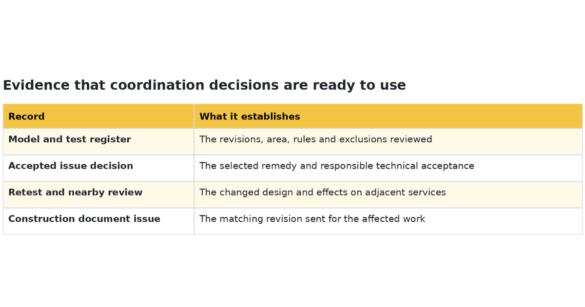
A falling clash count is not, by itself, proof of better construction readiness. Counts can change because objects were removed, exclusions changed or models were incomplete. Review significant unresolved issues, overdue decisions and whether critical work areas have accepted coordination records.
For cost reporting, distinguish potential exposure from evidenced savings. Record what work had been committed, the approved remedy and any verified fabrication or installation changes. Claim an avoided cost only where the baseline and assumptions are credible; do not multiply every software result by a standard saving.
Useful measures include time to resolve priority issues, recurrence after model updates and packages released with complete evidence. These measures connect BIM clash detection to actual project decisions without suggesting that software guarantees a particular budget outcome.
Autodesk’s results and status guidance shows why status labels must be understood: reviewed, approved and resolved carry different meanings.
A model can only test the information and rules supplied. It does not automatically verify hydraulic performance, electrical calculations, construction quality or compliance with the Saudi Building Code. Separate discipline reviews and applicable project approvals remain necessary.
Installation sequence and temporary access also need consideration. A finished arrangement may fit while a large duct section cannot be lifted into position after neighbouring work is installed. Review construction methods with the contractors; static clash tests do not automatically establish that sequence.
Finally, a “clash-free” label needs a stated scope, model revision and accepted exceptions. It should mean that the agreed tests have been reviewed for the named area. It should never be interpreted as a guarantee that every possible site problem has been eliminated.
Before authorising an affected package for fabrication or installation, request three records: the tested model revisions, the decisions on significant conflicts and the coordinated issue of the construction documents. Confirm who accepted each technical solution and what remains outstanding.
At the coordination meeting, ask: “What could stop the next planned activity, who must decide it, and when does the contractor need the revised information?” Focus the review on the work ahead. Track the answer through retesting and document issues, instead of closing the discussion when a screenshot has been marked up.
Crown Axis provides digital engineering and BIM coordination services including MEP coordination and clash detection. If your Saudi project has congested service zones or unresolved interfaces, share the current drawings, model revisions and upcoming construction packages to discuss a suitable coordination scope.
For linked design development, its MEP design services cover coordinated building systems.
Contact Crown Axis to discuss the project requirements and information available.
Yes, if the review is proportionate to the congestion and consequences. A compact fit-out with a shallow ceiling zone can have significant coordination needs. Target the critical areas and interfaces rather than modelling unnecessary detail. The scope should reflect the decisions the team needs to make and the information it can reliably provide.
Not necessarily. Teams can coordinate through agreed exchange formats and compatible review tools. They still need to validate coordinates, geometry and the information transferred. Agree file versions and issue-management procedures early. A successful export alone does not prove that every required element or property was retained accurately.
Not always. Some tools allow a finding to remain accepted even though its geometry still intersects. For example, an intended connection may receive a documented acceptance. Check the project’s status definitions and justification. Technical closure should explain whether the geometry changed or the responsible reviewer accepted an intentional condition.
Coordination records can help document when an issue was identified and which revisions or decisions followed. They do not establish contractual entitlement by themselves. Retain the relevant notices, instructions and cost records under the project contract. Any claim needs assessment by the responsible commercial team using the actual circumstances.
Browse through some of our proudest builds and transformations
We prioritize attention to detail and use high-quality materials for lasting, exceptional results.
We prioritize attention to detail and use high-quality materials for lasting, exceptional results.