
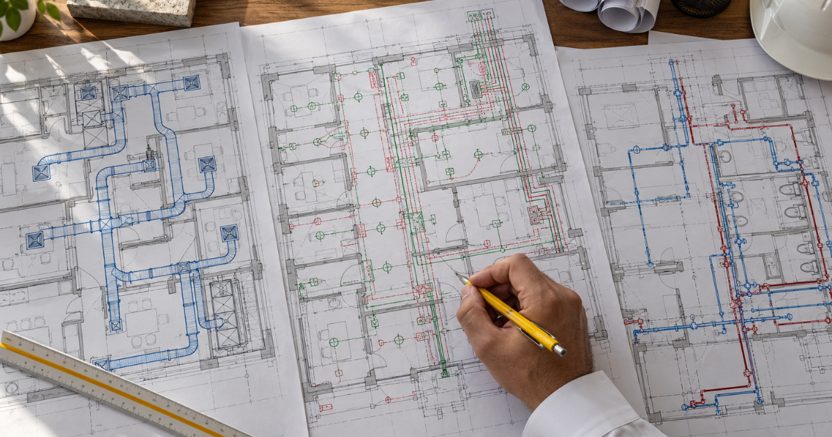
An MEP shop drawing review checks whether the proposed installation matches the project’s design, specifications, selected equipment and site conditions. Reviewers need to check mechanical, electrical and plumbing details individually, then confirm that their connections and shared spaces agree. Each unresolved issue should have a clear action and a record of how it was closed.
For Saudi construction projects, the review basis also includes applicable Saudi Building Code requirements and project-specific authority conditions. This MEP shop drawing review checklist explains what to inspect before releasing an installation package. It covers commercial and industrial building services; specialist process systems need their own review criteria.
Shop drawings describe how the contractor proposes to fabricate, assemble or install the work. Design drawings establish the engineering requirements and arrangement. Manufacturer product data identifies the selected equipment, accessories and performance. These documents serve different purposes and should be reviewed together.
Start with a controlled set of design drawings, specifications, equipment schedules, approved product submissions and documented design changes. Include relevant requests for information (RFIs): written questions used to clarify missing or conflicting project information. Confirm which responses have been formally incorporated into the design.
Agree the contractor’s internal checks, consultant review scope and release procedure through the project documents. Do not assume that a review stamp carries the same meaning on every Saudi project. A shop drawing review should not silently authorise a substitution or design change; identify deviations explicitly and obtain the required decision.
For terminology, see AIA’s explanation of construction submittals. Its contract examples are not universal Saudi obligations; use the project’s own agreement for responsibilities.
| Check | Reference | Action if Inconsistent |
|---|---|---|
| Equipment tag | Schedule and selected product data | Identify affected sheets and confirm selection |
| Service level | Coordinated section and site survey | Clarify the level reference and verify space |
| Electrical connection | Equipment data and electrical design | Refer mismatch to the electrical designer |
| Drainage connection | Invert schedule and connection survey | Verify the receiving level before release |
Confirm the drawing number, title, discipline, building, floor, zone, revision and issue purpose. Compare them with the submission register. A current sheet can still refer to an obsolete detail, so check section references, schedules and continuation drawings as well.
Verify that architectural, structural and MEP drawings use compatible grids, units and level references. A pipe centreline, duct underside and drainage invert describe different positions. The invert is the inside bottom of a pipe. Require labels that make the reference clear rather than relying on an unexplained elevation number.
Check equipment tags against the schedules and room names against the current layout. Confirm which dimensions have been field verified and who owns the remaining measurements. Where an existing shaft or slab differs from the design, raise a recorded discrepancy before developing a route around it.
Mechanical shop drawings should make each route and connection understandable. Check duct sizes, airflow references, fittings, transitions, branch connections and terminal locations against the design. Review pipe sizes, system identification and valve arrangements. Insulation and protective finishes add to the installed space requirement; bare-service outlines can understate the envelope.
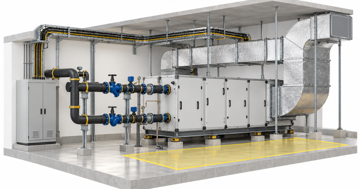
Compare equipment orientation and connection positions with the selected manufacturer’s data. Check that access is available to filters, coils, motors, strainers and serviceable components. The drawing should also account for removal or replacement, not merely the space occupied by the equipment when installed.
Review condensate drainage from the equipment to its intended discharge point. Ask the mechanical designer to confirm the required fall, trap or pump arrangement for the selected unit. Do not apply one generic drainage detail to every pressure condition or equipment type.
Identify supports, flexible connections and vibration isolation where required by the design. Confirm that proposed support locations can be coordinated with the structure. Changes to duct routes or fittings may affect pressure losses, so refer material departures to the designer for assessment rather than accepting them as drafting adjustments.
A technical reference example is the UFGS HVAC air distribution specification, which includes detail-drawing requirements. It is a US guide specification, not a Saudi project requirement unless adopted.
Electrical shop drawing review should connect every major equipment tag to its power source and connection requirements. Compare the selected equipment’s voltage, phase, frequency and electrical characteristics with the panel schedule and connection drawing. A supplier substitution can change these requirements even when the equipment serves the same function.
Check circuit and panel references across layouts, schedules and single-line diagrams. A single-line diagram represents the electrical distribution using simplified connections. Confirm that the responsible electrical designer has checked cable and protective-device selections against the approved equipment data and project requirements.
Review cable tray and conduit routes, supports, bends, crossings and entries into equipment. Coordinate the space needed to install and maintain the system. Check earthing and bonding details against the approved design. Do not infer an acceptable separation or working clearance from a diagram that simply looks uncluttered.
Locate local isolators, controls panels and interfaces with mechanical equipment. Confirm who supplies the final connection, control wiring and commissioning support so these items do not fall between subcontractor packages.
The UFGS interior distribution specification distinguishes electrical shop drawings from product data; the project specification determines the actual submission scope.
Plumbing shop drawings should identify the service, pipe material, size, direction and connection points. Compare fixture and equipment references with the architectural layout and supplier information. Check valves, isolation arrangements, cleanouts and other service points for accessible locations.
For gravity drainage, review the longitudinal levels as well as the plan route. Show pipe falls, invert levels and the receiving connection. A route may fit in plan while lacking the vertical space needed to reach the discharge point. The engineer should establish the applicable slope and sizing requirements; this checklist does not prescribe universal values.
Coordinate risers and branches with shaft space, floor openings and equipment connections. Confirm the intended access to concealed service points and the relationship between drainage details and finished floor levels. Where a connection remains unverified, record the missing information rather than presenting a provisional level as confirmed.
Include supporting calculations or technical submissions where the project requires them. A detailed-looking drawing cannot establish hydraulic performance on its own.
The UFGS plumbing specification provides an example of plumbing detail-drawing and supporting-information requirements.
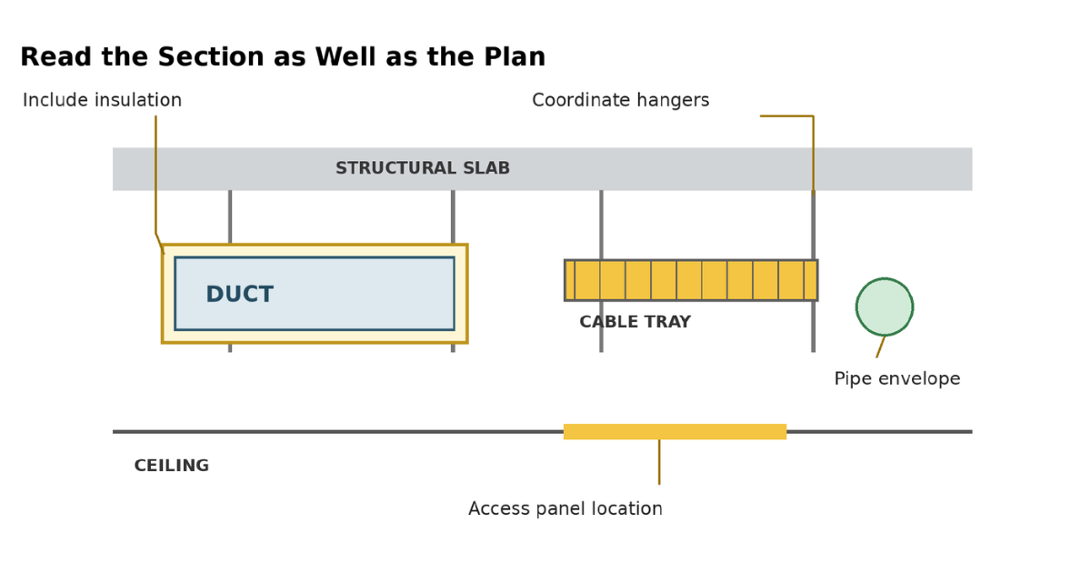
Use coordinated MEP drawings to review the actual section through congested areas. Plans show horizontal routes; sections help establish how ducts, pipes and cable trays fit between structure and ceiling. Include insulation, hangers, fittings and access panels in the spatial review.
Link proposed sleeves and openings to an opening schedule with grid position, level and dimensions. Structural penetrations and service supports need the responsible structural designer’s review. A note saying ‘coordinate on site’ is insufficient where the proposed work depends on an unresolved structural decision.
Review fire-rated wall and floor penetrations with the relevant specialist. Identify the required penetration protection and applicable tested or approved system for the actual services and construction. Fire dampers, inspection access and fire-system interfaces should remain consistent with the fire strategy and approved design.
Confirm responsibility for ceiling access panels, builder’s work and equipment replacement routes. A successful BIM coordination check supports this review, but it does not verify product selection, design calculations or every drawing annotation.
Record the Saudi code edition and authority requirements applicable to the project. Relevant code families can include SBC 401 for electrical systems, SBC 501 for mechanical systems, SBC 701 for plumbing and SBC 801 for fire protection. Non-residential energy provisions may also affect the design. Confirm applicability with the project’s responsible professionals.
For MEP shop drawings in Saudi Arabia, the submission matrix should identify who reviews each package and whether any separate authority submission is required. Municipal, industrial-development, landlord and utility requirements depend on the location and scope. Consultant review and authority approval are distinct processes.
Keep the checklist tied to the approved engineering basis. Do not introduce foreign specification requirements as Saudi law, or treat one client’s stamp codes as a national standard. Resolve any conflict between requirements through the agreed project procedure.
Confirm the code families through the official Saudi Building Code portal and verify the requirements that apply to the actual project.
A useful review comment identifies the drawing, revision, location and discrepancy. It then states the required correction or information and the reference that supports the request. Avoid comments such as ‘check electrical’ when the actual issue is an equipment tag connected to a different panel on another sheet.
Give each significant comment a reference and responsible party. Record whether closure requires a revised drawing, a designer’s calculation, a supplier confirmation or an accepted RFI response. Distinguish an information request from a proposed design change.
On resubmission, compare the response against the changed sheets. Review revision clouds and the change summary, including changes introduced beyond the original comments. A statement saying ‘done’ should point to the correction. Keep the original comment and closure evidence together so the decision remains traceable.
| Vague Comment | Traceable Review Comment |
|---|---|
| Check electrical | EF-01: connection sheet names a different panel from the schedule. Confirm the source and revise both references. |
| Provide access | Section A: show filter removal space against selected AHU data and coordinate the ceiling access opening. |
| Done | Response: identify revised sheet and detail; attach the supporting confirmation for reviewer closure. |
Consider an illustrative Riyadh commercial project where a contractor proposes a different extract fan. The mechanical equipment schedule is updated, but the electrical connection drawing and controls diagram still describe the original selection. There may be no physical clash, yet the package is inconsistent.
The reviewer identifies the fan tag and requests the selected manufacturer’s performance and electrical data. The mechanical designer checks the duty and connection arrangement. The electrical designer reviews the supply and protection requirements. The controls team confirms the command, status and any required interlocks for the selected equipment.
The contractor then updates the affected schedules, connection details and coordinated drawings, with the substitution decision recorded separately. Closure means that the linked documents agree and the required reviewers have accepted the changes under the project procedure. Updating one schedule alone would leave the installation team with conflicting instructions.
Before releasing an area, ask the discipline leads to identify the exact drawing revisions and work included. Confirm that review conditions affecting that installation are closed, or that any permitted partial release has a clearly documented boundary and authorised decision.
Check that the site team can access the released drawings and supporting details. Withdraw superseded versions from active use and communicate revised instructions to the affected trades. Match the release to fabrication and installation dates so unresolved items are visible before dependent work proceeds.
Record who authorised the release, its date and any exclusions. Review completion does not replace site inspection, testing or commissioning. Those activities still need to confirm that the installed work follows the accepted documents and project requirements.
| Confirm | Record |
|---|---|
| Work boundary | Building, zone, system and exclusions |
| Current information | Drawing numbers, revisions and linked details |
| Conditions closed | Reviewer acceptance and supporting evidence |
| Site communication | Released set distributed; obsolete set withdrawn |
| Authorised decision | Responsible person, date and remaining restrictions |
Crown Axis provides MEP design services and digital engineering and MEP coordination in Saudi Arabia. If your Saudi project needs clearer coordination between drawings and installation requirements, share the current drawing set, selected equipment data and outstanding review comments. Contact Crown Axis to discuss a suitable engineering scope.
Yes, when the proposed equipment changes information that the reviewed package relies on. Connection positions, electrical data, controls, dimensions or maintenance access may differ. Identify the affected drawings and submissions, obtain the required substitution decision, and follow the project’s resubmission procedure. The extent of review depends on the actual changes; a new brand name alone does not describe their technical impact.
Record the measured discrepancy, location and method of verification, then refer it to the appropriate project team. Avoid moving services or altering structural elements through an informal site instruction. The response may require revised routing, a design check or updated builder’s work information. Incorporate the accepted solution into controlled drawings so subsequent trades work from the same decision.
A partial release may be possible if the contract and project procedure allow it and the authorised team defines its limits. The released area must not depend on unresolved connections, levels or interfaces elsewhere. Record the permitted work and exclusions clearly. A drawing status alone should not be interpreted as permission for every related activity across the building.
Reviewed shop drawings describe the accepted proposal for installation. As-built drawings record the installation as completed, including documented changes. They should be checked against site records and the project’s handover requirements. A reviewed shop drawing becomes an unreliable as-built record if it is simply renamed without confirming that the actual routes, equipment and connections match it.
Browse through some of our proudest builds and transformations
We prioritize attention to detail and use high-quality materials for lasting, exceptional results.
We prioritize attention to detail and use high-quality materials for lasting, exceptional results.